Table of Contents
ELV files and photoshop
Purpose
The purpose of this tutorial is to help understanding how the elevation values in a .elv (or .ex file) are stored and how is that visualized when opening these files with Adobe Photoshop (or similar programs) as raw images.
The elv file
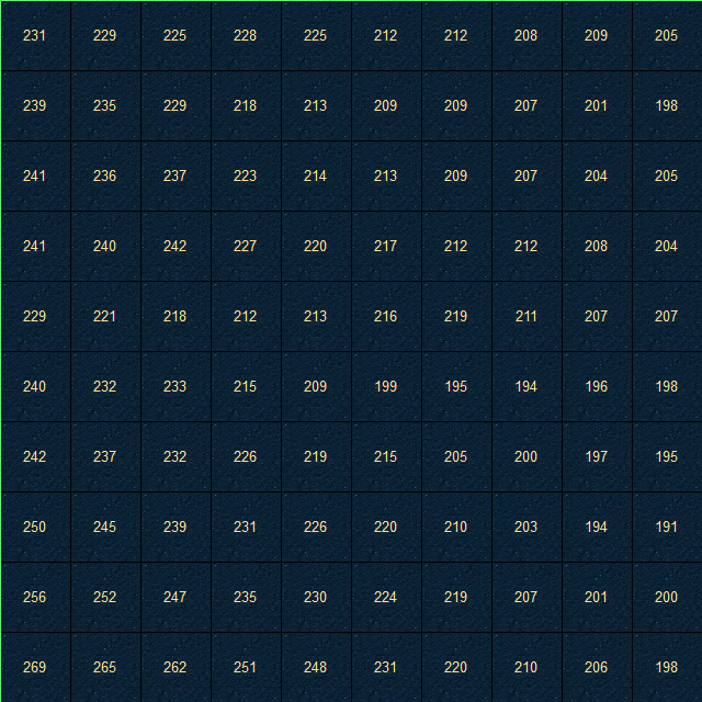
For the purpose of this article, we will use a small elevation file that is just 10×10 points (100 elevation values). The elevation data we are going to use are showing in the picture below:

These elevation data are saved in the disk in a binary format of short, meaning, each elevation value is represented with two bytes. If we open the values in a hex editor, we get these values:

The first two bytes (0D 01) represents the lower left corner (269 ft), the next two bytes represent the second elevation in the row etc. When you reach to the end of the line on the right side, the next two bytes represent the most left point on the row above. So we have totally 10×10=100 elevation points and because each point is represented by two bytes, our sample elevation file is 100×2=200 bytes long.
Let's take the first elevation value and examine it for a while. We know that 0D 01 represents 269 but how exactly is it computed?
Each pair of numbers holds the value of the byte it represents. Byte value range is from 0 to 255. These values are represented in hexadecimal format so what we can expect to see in each byte slot is a value from 00 to FF. In our case, the first value is 0D which is 13 in decimal format (let's call this A) and the second is 01 which is 01 (again) in decimal (let's call this B).
To calculate the final elevation from these two values, the formula is simple:
In our example, setting A=13 and B=1 we get
 For the rest of this article, we'll assume the elevation values are unsigned, that means we only calculate positive results. That's not the case even in Falcon since elevation can have negative values. For further reading take a look at Signed number representations and Integer (computer science).
It's obvious why we need two bytes to store elevation. If we only had one byte, the allowed values would be between -128 to +127 (signed byte). Now that we have two bytes, the signed range of elevation is −32,768 to +32,767 which is more than enough to represent elevation of ground points.
Another observation from the information above is that, the first byte (A) is getting big values easier than the second byte (B). You'll have to have big elevation values in order to have big values in B.
Getting raw images in Photoshop
Opening Photoshop (PS from now on) and selecting in the menu File→Open As…, you are able to import these elevation data as a raw image and have a visual representation of them. The dialog you get from PS after selecting the file is:

I'll describe the settings in this dialog, in order to understand what happens and what you'll get with different settings. Remember, we have a file with 100 As and 100 Bs and each A and each B is one byte long.
Dimensions
This one is simple. This tells PS how many rows and columns of data we have. These values are often guessed correctly by the program. In our case both values are 10.
Channels
This is the part that you can tweak in order to get the representation you want. PS is getting data and store them in Channels. It expects to read from the file these data but you have to tell how these data are stored. Furthermore, each channel should have the amount of data defined by Dimensions, in our case 10×10=100 data points (not bytes, just data points in general). The format of each data point is specified by the following options:
Count
The number of the Channels that PS will try to import. The value here depends on the format of your file and the other values in Channels field.
Interleaved
If the Channel data are stored in an interleaved format it means that all the Channel data for every point are stored together, so if C1,C2 etc are data for Channel 1, Channel 2 etc, we'll have:
C1,C2,C3…,C1,C2,C3…,C1,C2,C3…
The other option is to have all the Channel 1 data stored together, then store the Channel 2 etc:
C1,C1,C1…,C2,C2,C2…,C3,C3,C3…
Depth
How many bits each Channel data point is represented by. You can only choose between 8 (1 byte) or 16 (2 bytes). When you select 16, the other two options are available, so you can specify how PS is to represent the two bytes (either IBM PC or MAC). More on that later.
Header
You can specify if you have some extra bytes in the beginning of your file so PS won't try to read them (but when you save the file, you can choose to save this header as well).
Our Example
Now we know what every option in this dialog does, let's open our sample file. Let's set the options as they are displayed in the picture above. So we have a 10×10 grid with two channels, every point of each channel is 8 bit long (1 byte) and the channel data are interleaved.
So essentially we tell PS to open all the As in one channel and all the Bs on another. That's what we get from that.
We get two channels as expected, Alpha 1 and Alpha 2.

And these are the images of the two channels.


Remember, PS starts drawing values from the top of the image and our data start from the bottom, so to get a correct representation you need to Flip Vertically your image. For the purpose of this article, we'll keep the original images (no flipping).
We see different shades of gray on each point and the initial feeling is that we have a good visual representation of elevations. The lighter the color, the bigger the elevation value, right? But with a second look something is not feeling right. First of all, the Alpha 2 channel is completely black. Also, the first three points from the top-left point of the image in Alpha 1 are completely black, indicating a low elevation, but these values should be 269, 265 and 262 (not flipped, remember?). The next point with an elevation value of 251 is almost completely white. What's going on here?
 My understanding, on how
 PS is assigning color values on pixels is that, PS is setting value percentages. When you open an image, PS reads all the values and sets the percentage of a given pixel according to their value in the 0-max range, where max is 255 for 8bit and 65535 for 16bit (probably only unsigned values). You can actually get the percentage of a pixel by hovering your mouse over it and see in the Info panel, the percentage under K field.The actual Channel Data
Remember the As and Bs? Lets put in a table the first four elevation values of our file (h stands for hexadecimal representation and d for decimal).
| Elevation | A | B |
|---|---|---|
| 269 | 0Dh (13d) | 01h (1d) |
| 265 | 09h (9d) | 01h (1d) |
| 262 | 06h (6d) | 01h (1d) |
| 251 | FBh (251d) | 00h (0d) |
So we start to see what's happening here. The first value of 269 it gives two very small values in the two channels (13 and 1). The same happens for the next two points, but 251 although it's smaller than the previous values, it gives a big value in Alpha 1 and a small in Alpha 2. So that's why it appears almost white (251 out of 255 which is the max value for Alpha 1). On the other hand, the difference in Alpha 2 is not noticeable (changed from 1 that the prevous values had, to 0).
But the problem comes with the conclusion of all this: This kind of representation of elevations is not intuitive or safe to edit directly from PS.
You can't just say that the whiter a pixel is, the higher the elevation on that point is. As we saw, you can have (almost) black pixels in both channels, that are higher in elevation than other, whiter pixels. Also, when you edit any channel, you just edit As and Bs. So in Alpha 1, you just add or subtract (depends on whether you make the pixel lighter or darker) feet in the range of 0-255. In Alpha 2, you add or subtract multiples of 256.
But, if this no good to use, is there something else to use? Well, we have some other option in our Raw Import dialog, right?
16 bit and byte order
The obvious thing is to tell PS to load all two bytes of each value into one channel. There we know that the value of each pixel corresponds to one elevation value and we don't have to do calculations between channels.
The way to do this is to type 1 in Channel Count, select 16 bits and select one of the two byte order options. But, wait… Which one I should choose?
Byte Order
The byte order options tells PS how to calculate the final elevation value from As and Bs. Earlier I gave you the function which calculates the elevation from A and B.
That equation corresponds to IBM PC byte order. The equation for Mac byte order is:
See the difference? In our example, for setting A=13 and B=1 we get:
IBM PC byte order :
Mac byte order :
That's a huge difference… But which one we should use?
In my opinion, the byte order should be IBM PC which is the most accurate for our computers and Falcon. When you select Mac byte order, although you probably can make changes and
it might saved correctly, it's not intuitive. The lightness of the pixels doesn't mean higher elevations and vice-versa.
 Actually this byte order thing has a name. It's called Endianness. The
 IBM PC method uses LITTLE ENDIAN, while Mac method uses BIG ENDIAN.Editing
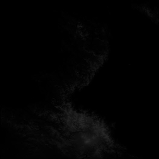
Let's open a Korea elevation file with this method. Using 1 channel, 16 bit and IBM PC byte order, we get this:

Well, it is a little disappointing, right? I mean, I can see a bit of the mountains in the north (we need to flip it, remember?) but where is the rest?
The range of values that each pixel can receive now is bigger (65536 vs 256) so, because our map contains relatively small elevation (I mean, 3.000ft is small compared to 65.535ft), black is the dominant color here. Can we brighten up the things a little? Sure…
In PS menu select Layer→New Adjustment Layer→Levels…. Then you have a layer that adjusts the level output of all the layers beneath it, so we can use it to brighten the picture.
 The reason to use an adjustment layer instead of applying the levels adjustment directly to the layer is that, you need to remove the adjustment before you save your elevation, otherwise the file will be saved with very big values. Applying a levels adjustment directly to the layer, cannot be undone later. With the adjustment layer, just hide or delete it before saving.
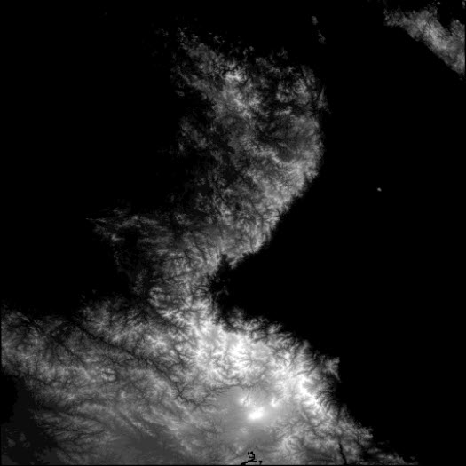
In the adjustment layer controls, adjust the sliders as you need, or better yet, press the Auto button. This will give the best result.

Better, right? Now you can start and draw anything you like, modifying the Korean elevation. Just a couple of thoughts before you continue.
Things to consider
If have the Color window open, you'll see that instead of actual color, you can select a percentage.

100% means black (or 0 elevation) and 0% means white (or 65.535 elevation). Wait… can't be 65535 since we can have negative elevations and the positive ones go up to 32.767.
Exactly, PS can only display unsigned elevations. So if you set a pixel to a value less than 50% (or so) it will be negative in Falcon.
Another thing to consider is the elevation change by changing the color 1%. Because it's a percentage, the smaller elevation change you can achieve (1%) is:
So you can only edit elevations in multiples of 655ft.
